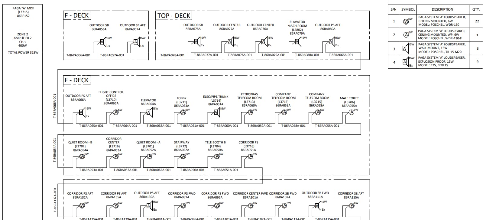
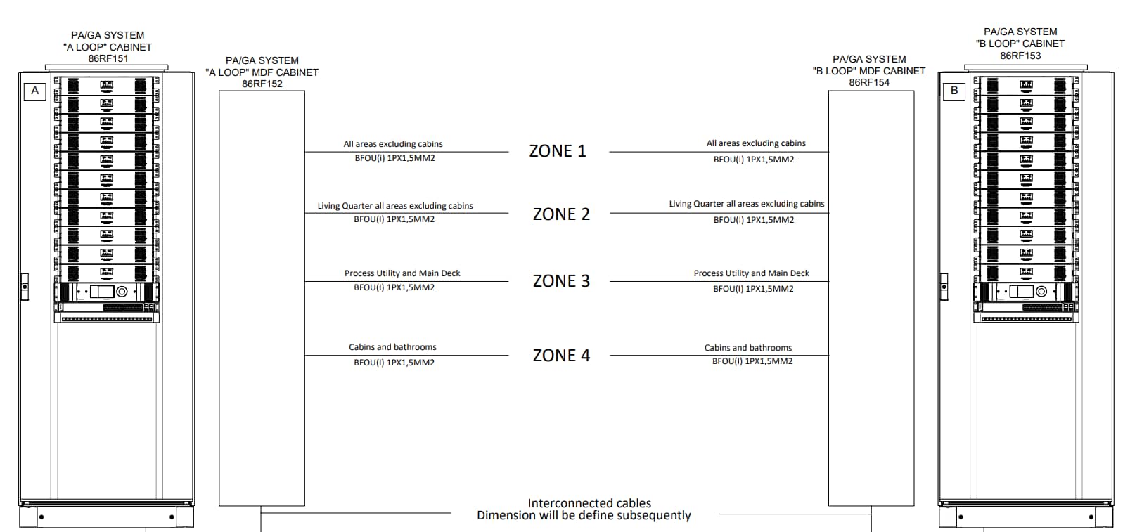
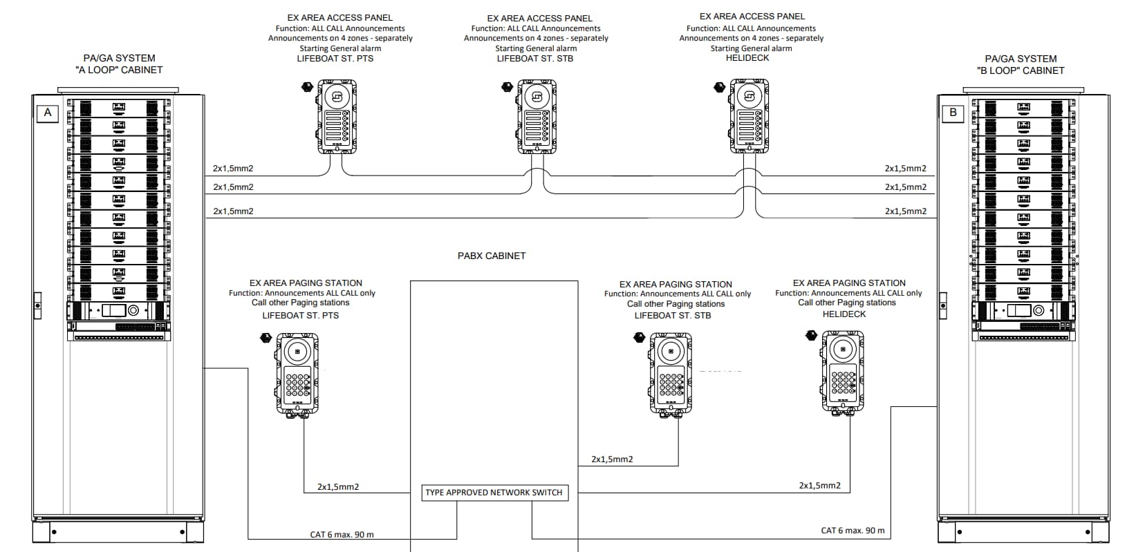
In the oil and gas industry, where safety is paramount, understanding cable block diagrams of PAGA systems is important.
These systems rely on complex cabling arrangements to ensure seamless audio transmission and control signals. Cable block diagrams provide a comprehensive visual representation of these arrangements. This enables engineers, technicians, and operators to understand and maintain PAGA systems effectively.

Components of Cable Block Diagrams for PAGA Systems
Central Control Room
The cable block diagram typically includes the central control room where PAGA system control panels are located. These control panels enable operators to manage audio broadcasts, control alarm zones, and monitor system status..
Field Equipment
The diagram illustrates field equipment, including loudspeakers, amplifiers, microphones, and interface units, spread across various locations in the oil and gas facility. These components are strategically placed to ensure effective coverage and communication throughout the facility.
Cable Types and Specifications
Oil and gas facilities often require cables capable of withstanding harsh environmental conditions. The diagram specifies the types and specifications of cables used, such as fire-resistant, armored, or intrinsically safe cables, to meet industry standards and ensure reliable performance.
Hazardous Area Classification
Cable block diagrams in the oil and gas industry incorporate hazardous area classifications. They outline the designated zones (e.g., Zone 0, Zone 1, or Zone 2) where specific types of cables and equipment must be used to mitigate the risk of igniting flammable substances.

Key Features of Cable Block Diagrams for PAGA Systems
Redundancy and Fault Tolerance
Oil and gas facilities prioritize system reliability. Cable block diagrams showcase redundancy measures, such as duplicate cables and backup amplifiers, to ensure uninterrupted communication in case of cable or equipment failures.
Cable Routing and Sealing
Due to the presence of flammable gases or liquids, cable block diagrams emphasize proper cable routing and sealing techniques. These measures prevent the ingress of hazardous substances and maintain the integrity of the system.
Communication Interfaces
PAGA systems in the oil and gas industry often interface with other systems, such as the plant's Distributed Control System (DCS). The diagrams outline the communication interfaces and protocols employed to enable seamless integration and exchange of signals between systems.
Power Supply and Grounding
Cable block diagrams include information about power supply connections and grounding points. Proper grounding is critical to mitigate electrical hazards and ensure system stability and performance.

Importance of Accurate Cable Block Diagrams
Due to the critical nature of PAGA systems for organizations in the oil and gas industry, accurate cable block diagrams are important. Accurate diagrams will help ensure safety compliance by providing a clear overview of the cabling infrastructure, facilitating proper installation, maintenance, and troubleshooting of PAGA systems.

